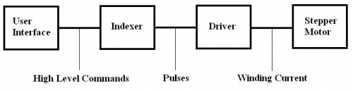
Motors Mechanics Power and CNC Circuit Diagram Fig. 2: Stepper motor working principle. Working of Stepper Motor. Generally, stepper motors are operated by electronic circuits, mostly on a dc power supply. The drive systems of stepper motors are classified into open-loop and closed-loop drives. Fig. 3 illustrates the block diagram of a modern driving system for a stepper motor in open-loop Arduino Stepper Motor Position Control Circuit Diagram and Explanation: The circuit Diagram for the arduino stepper motor control project is shown above. We have used the 28BYJ-48 Stepper motor and the ULN2003 Driver module. To energise the four coils of the stepper motor we are using the digital pins 8,9,10 and 11.

Stepper motor types: 4, 5, 6, or 8 wires. 4 and 5 wires are fixed. 6 and 8 wires are changeable.; Wiring options: Unipolar, bipolar series, bipolar parallel, or bipolar half coil.Each has different performance and current. Wiring methods: Depends on the number and color of wires.Use datasheet or guide to connect to driver terminals.
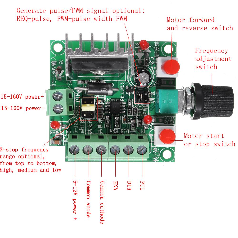
Stepper Motor Circuit Diagram
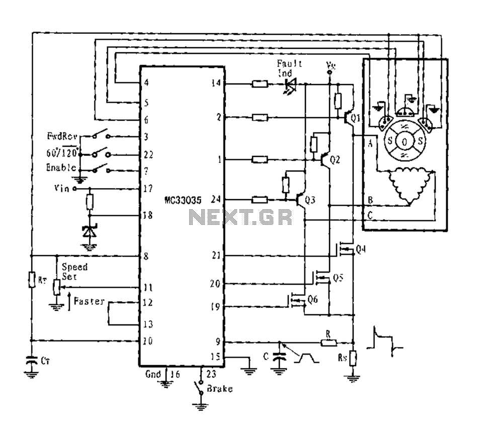
Learn how to build a simple stepper motor controller using four transistors, two NOT gates, one XOR gate and diodes. The circuit diagram shows the parts list, the control logic and the power supply for the motor.
Wiring diagram/schematic for A4988 stepper motor driver with Arduino and stepper motor. The wiring diagram/schematic above shows you how to connect the A4899 driver to a stepper motor and the Arduino. The connections are also given in the following table: A4988 Connections. A4988 Connection; VMOT: 8-35V: GND:
How to Wire a Stepper Motor (4, 5, 6, and 8 Wires) Circuit Diagram
And hence, this Stepper Motor Driver Circuit is essentially a Binary Counter Circuit. Stepper Motor. A 12V Stepper Motor is used in this project. It is a Unipolar type Stepper Motor with 5 - wire configuration. Basically, Stepper Motors are classified in to Unipolar Stepper Motors and Bipolar Stepper Motors, based on the windings of the stator. The circuit diagram has a two-stage stepper motor driver. Here the timer IC 555 works as an astable multivibrator to generate a clock or a square wave. And produced a square pulse based on the timing resistor and timing capacitor. The frequency of clock generation, in this case, cannot be kept constant so we need to get a variable speed for the