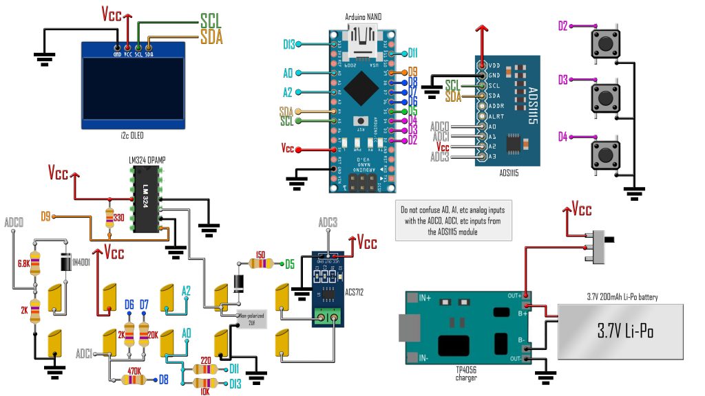
DIY 6digit multimeter Circuit Diagram How to make multimeter at home. How to create a digital voltmeter and ammeter. DC polarization test _ Creative channel. Today I created my own voltmeter an This is a project based on Arduino board which can measureresistance, diode, continuity[H1] , voltage,[H2]current[H3] , power[H4] , hfe[H5] and capacitance[H6] .The values are displayed onthe 16*2 LCD. The project uses an Arduino pro mini boardwhose ADC feature is used along with the concepts like Voltage divide,Ohms law, RC charging are used to develop this Multi-meter. The multimeter is an indispensable tool for any electronics project, as it helps overcome countless challenges during project completion. This article will demonstrate how to create a cost-effective digital multimeter using an Arduino board and an OLED display.This multimeter is capable of measuring voltage, current, resistance, and capacitance.
How To Make A Multimeter || Digital Multimeter || Diy Multimeter Warning :- Have Fun But Always Remember To Be Safe, Anything You Try Is At

How To Make A Multimeter Circuit Diagram
In this project, you will be building a voltmeter and ohmmeter using the digitalRead function of an Arduino.You will be able to get a reading almost every millisecond, much more precise than a typical multimeter.. Finally, the data can be accessed on the Serial monitor, which then can be copied onto other documents, e.g. excel, if you want to analyze the data. A multimeter is a must-have tool in your arsenal when it comes to creating or developing electrical circuits. Without it, executing a job will be extremely t The Blueprint: A Step-by-Step Guide. Now, let's dive into the step-by-step process of building your DMM: 1.Circuit Design: Begin by sketching a basic circuit diagram on paper, outlining the connections between components. This serves as a visual roadmap for your project. 2. Microcontroller Programming: Write a program for your chosen microcontroller using a suitable programming language like

Step 9: To calibrate a homemade shunt resistor, you will need to connect your multimeter assembly to a calibrated source of high current or a high-current source in series with a digital ammeter for reference. Use a small metal file to shave off shunt wire thickness or to notch the sheet metal strip in small, careful amounts.