Controlling a gate with LoRa boards Circuit Diagram For the transmitting side we will use an Arduino UNO with our LoRa module. The circuit diagram to connect the Arduino UNO with LoRa is shown below . The LoRa module consists of 16 pins with 8 pins on each side. Out of these 16 pins, six are used by GPIO pins ranging from DIO0 to DIO5 and four are used by Ground pins. The module operates in 3.3V

This circuit connects an Adafruit RFM9x LoRa Radio module to an Arduino MKR WiFi 1010 for wireless communication capabilities. The LoRa module's SPI interface (MOSI, MISO, SCK, CS) is connected to the corresponding SPI pins on the Arduino, allowing for serial data transfer between the devices. Lora antenna circuit design issues, in fact, as long as you master a few major points, you can basically play the best performance of LoRa. Point 1, matching circuit design. When designing the schematic diagram, a π-type matching circuit needs to be reserved between the antenna connector and the antenna pin of the module. The impedance of the

4 Points Of LoRa Antenna Design Circuit Diagram
This circuit features an ESP32C3 Supermini microcontroller connected to a LORA_RA02 module and a DHT11 temperature and humidity sensor. The ESP32C3 handles communication with the LORA module via SPI (using GPIO05, GPIO06, GPIO10, and GPIO04 for MISO, MOSI, NSS, and SCK respectively) and GPIO01 and GPIO02 for additional control signals.
In the transmitter Lora circuit, we have connected the transmitter Lora module with Arduino Nano as per the circuit diagram. In the Transmitter Lora circuit, 5 push buttons are connected with Arduino digital pin D2, D3, D4, D5, D6. Whenever we press any push-button, the signal sent to receiving the Lora module to turn on or off the respective

How to Use WiFi LoRa 32(V3): Examples, Pinouts, and Specs Circuit Diagram
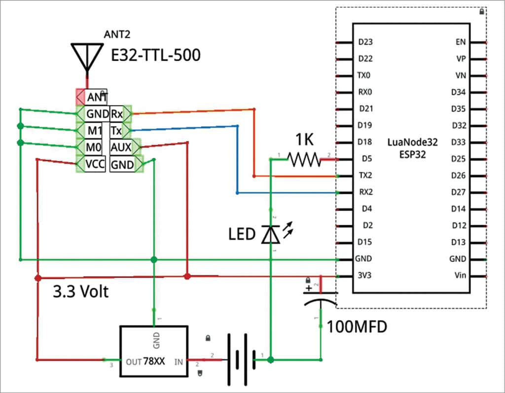
This circuit integrates an ESP32 microcontroller with a LoRa Ra-02 SX1278 module for long-range wireless communication. The ESP32's digital pins are connected to the LoRa module's SPI interface (MOSI, MISO, SCK, NSS) and control lines (RST, DI00) to enable data transmission and reception.